| |
| |
TIP 1
ADDITIONAL SOUNDS |
Guitarists sometimes
look for various modifications to the guitar
pickup connections to obtain some additional or
non-standard sounds.
For guitars like the Fender Stratocaster (S-S-S),
I propose an easy expansion of the sound palette
while maintaining the current connection layout
(with a 5-position switch), which is optimal and
works for the vast majority of needs.
This does not require any modification to the
guitar, only the use of a push-pull switch on
one of the potentiometers (e.g. Volume).
| - |
When the
push-pull switch is pressed, the
engagement combinations are as standard. |
| - |
When the
push-pull is pressed, the pickups engage
differently and provide additional
sounds. |
The presented "expansion" additionally provides
a very interesting sound option of
simultaneously switching on the bridge and neck
pickups, which gives a very wide sound: the
glassiness and dynamics of the bridge pickup are
combined with the depth and warmth of the neck
pickup.
This combination is obtained in positions 1 and
5 of the pickup switch.
The modification also allows simultaneous
switching on of all three pickups, to obtain a
maximum and full signal.
This combination is obtained in positions 2 and
4 of the pickup switch. |
 |
|
| |
TIP 2
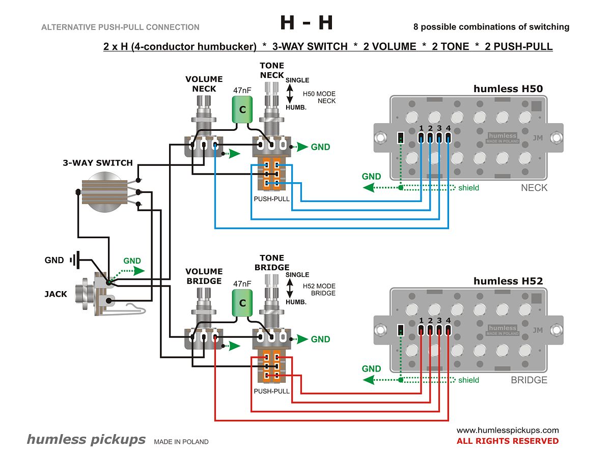
ALTERNATIVE COIL DISCONNECTION |
Almost 70 years ago,
P.A.F. humbuckers were invented. Not much later,
someone came up with the idea of disconnecting
the humbucker coils (to obtain a
quasi-single-coil sound) by shorting the winding
of one of them to ground.
And so the "brand standard" of connections was
born, which is still widely used today.
But anyone who studied physics (that from 190
years ago - about magnetism, induction,
self-induction, Fraday's law, Lenz's rule...)
can intuitively feel that shorting the pickup
coil in a variable magnetic field somehow
clashes with what they were taught in school.
Because: in a variable magnetic field (in the
pickup: from a locally vibrating magnetized
string), a variable voltage is induced in the
coil (the signal from the pickup). If we
short-circuit the pickup coil (e.g. to ground),
a self-induction current will flow in it, which
will counteract the changes in this field, and
therefore the vibrations of the strings.
Shorting one coil may therefore cause a certain
damping of the string vibrations, manifesting
itself in slightly less sustain, and in certain
cases also "dull sounds" (wolves) on individual
frets and strings.
This risk can be easily bypassed by using an
alternative coil disconnection system, in which
the coil winding is not short-circuited. |
 |
|
| |
TIP 3
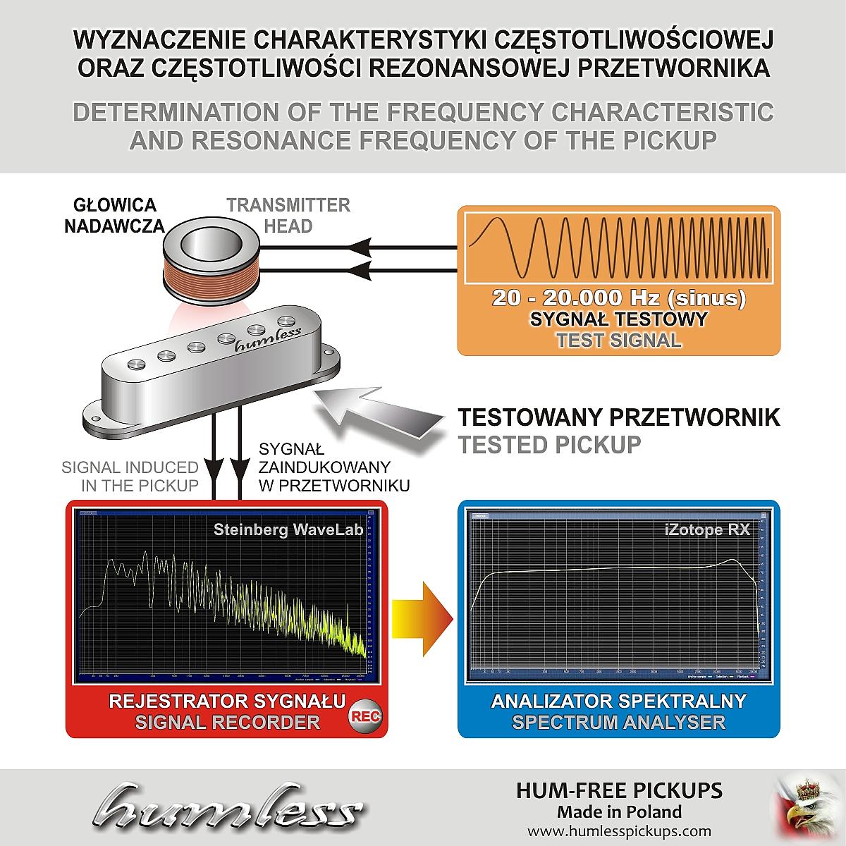
DETERMINATION OF THE
FREQUENCY CHARACTERISTIC |
 |
| |
| |
TIP 4
DETERMINING THE
PHASE OF A PICKUP SIGNAL |
When installing
different pickups from different manufacturers
in a guitar, it is important that their signals
are connected in phase.
This is a condition
for their proper operation – when two adjacent
pickups are switched on simultaneously, their
signals will add.
The phases of the
signals can be determined/compared using a
simple method.
For this, you need a DC voltage meter.
It is best and most
convenient to use an analog (pointer)
galvanometer with a center zero.
You can also use a
"regular" digital multimeter, setting it to the
0.2V DC voltage range.
Any object made of ferromagnetic steel, such as
the tip of a screwdriver, can be used to move it
through the pickup's magnetic field.
First, determine the phase of the existing
pickup's signal – this will be the reference for
connecting the "new" pickup.
Connect the DC
voltage meter to two signal pins of the pickup
being tested. Remember which of the meter's
wires is connected to the ground connection of
the existing pickup (e.g., black) and which to
the signal (e.g., red).
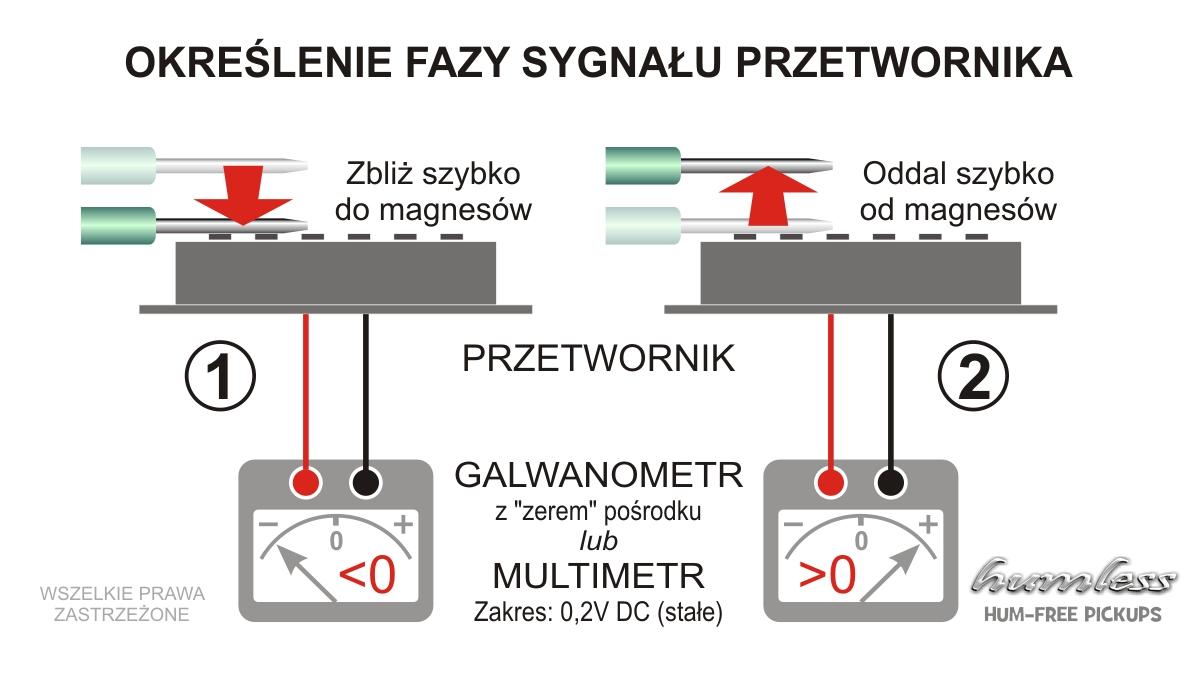
|
1. |
Quickly bring a
metal object close to the pickups's
magnets (until it touches the magnets)
and observe which direction the
galvanometer needle deflects momentarily
or which voltage sign the multimeter
indicates: positive or negative |
|
2. |
Quickly remove (tear
away) the metal object from the magnets
– the galvanometer needle will deflect
in the opposite direction and the
multimeter will indicate reverse voltage
polarity. |
NOTE: With a multimeter, due to the transient
readings – only when the metal moves in a
magnetic field – repeat the steps several times,
observing the voltage sign as the metal object
is brought close to the magnets and then removed.
Now you can use the
same method to determine the phase of the new
pickup's signal.
Connect its two
leads to the meter's wires and perform the same
steps, paying attention to which meter lead is
connected to which pickup lead.
If, when a metal
object is brought close to the magnets, the
momentarily induced voltage has the same sign as
in the previously tested pickup, this indicates
that the connection is in phase.
Then, connect the
pickup cable (connected to the black meter lead)
to the guitar ground, and the red one to the
signal path (pickup switch).
If the voltage that
appears has the opposite sign than when testing
the existing pickup, then reverse the wire
connections of the "new" pickup.
This method can be
used with any type of "standard" pickup,
including humbuckers. |
 |
|
| |
|